Heat-loss calculations
Design ambient, maintain temperature, pipe and vessel geometry, insulation performance and fitting allowances.
Calculations and documentation grounded in how industrial heating systems are selected, supplied, installed and operated.
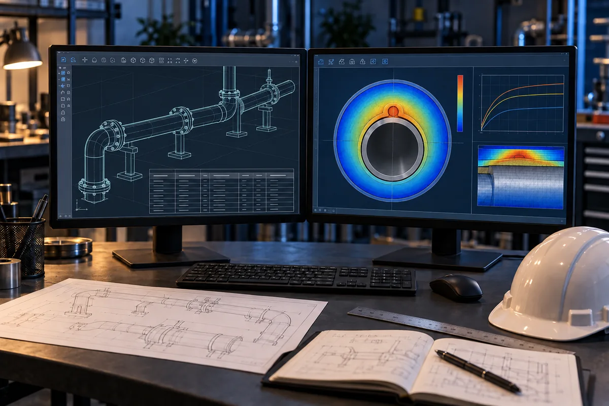
Design ambient, maintain temperature, pipe and vessel geometry, insulation performance and fitting allowances.
Thermal duty, maintain and exposure temperatures, installation environment and hazardous-area requirements.
Power distribution, protection, control philosophy, cold-start loading and circuit lengths.
Circuit schedules, cable quantities, connection and termination components, panels and instruments.
Cable routing, fixing, insulation interfaces, sensor placement and site coordination.
Test planning, checks, settings and operating guidance to support system handover.
Heat-tracing cable follows the outside of the pipe in straight parallel runs or an engineered spiral arrangement, beneath the insulation.
Use specified aluminum or glass-fiber adhesive tape to secure the cable directly to the pipe. Valves and flanges need external service loops and additional cable allowance. Keep cable clear of moving parts and observe the manufacturer’s minimum bend radius and fixing requirements.
Cables never enter pipe bores or pass through flange bolt holes. Detail the junction box with a power cable input and heating cable output. Drawings and installation details must match the selected cable system.
Our calculator estimates straight-pipe heat loss. EHT engineering review adds the installation, electrical and application detail needed for a final selection.
Open Engineering Calculator